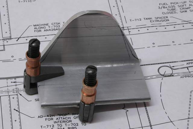
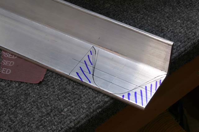
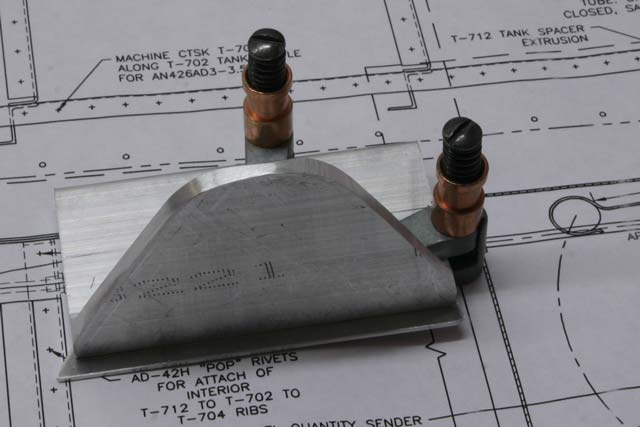
Fabricating Tank Attach Bracket October 22nd, 2007
First, I sketched out the outline in the angle. I used a hacksaw to cut it slightly to shape, and then used a belt sander for the final shape.


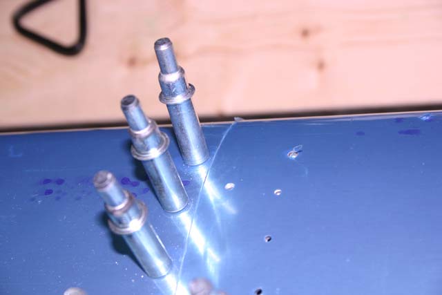
Drilling the Tank Skin.. October 15th, 2007
Nothing too exciting here… I took the tank off the wing and match drilled all the holes…

Fitting the Tank Skin October 9th, 2007
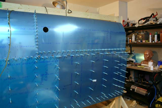
So, I decided to use the same method I used to fit the leading edge skin. I assembled the baffle on top of the spar, and clecoed the ribs to it. I also clecoed one side of the skin to the rivet holes. To keep the ribs from moving out of place when the skin is ratcheted down, I placed wood dowels between each rib. I made each little dowel to fit each individual rib, and yes, it was a pain in the neck, but in the end it was worth it.


Here is the end result…

Finally, I went back to check the leading edge to tank fit, and it couldn’t be any better…
Matching the Tank and Leading Edge September 23rd, 2007
In order to make sure the fuel tank and the leading edge match up as perfectly as possible, I assembled the baffle and tank skin on the spar (with no ribs), and moved it up to mate up with the leading edge. When they matched nicely, I drilled the baffle to the first two Z-brackets and put clecoes in.
I then removed the skin and drilled the rest of the baffle/Z-bracket holes.
Not too many pictures of this process; I have been busy helping with stuff around the house, and decided to focus my free time on building and not so much picture taking.
Drilling Tank Z brackets September 22nd, 2007


The result is a bracket with the holes nicely matching the spar holes..
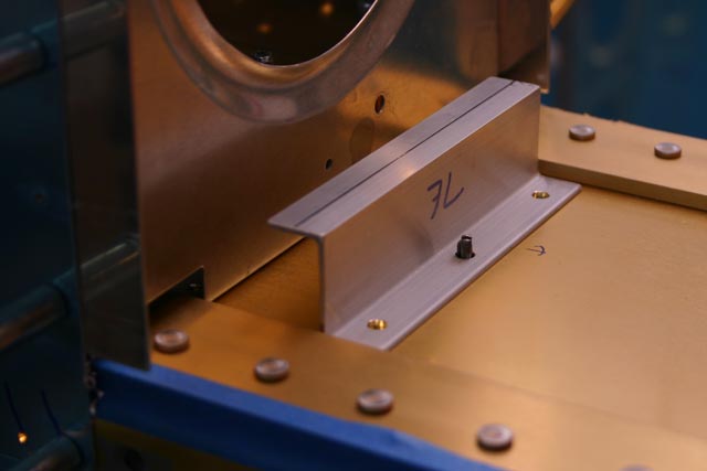
And here is the spar with the first z-bracket drilled and clecoed to it… 6 more to go on this wing..

The Tank Attach Holes (All 360 of them!) April 9th, 2007
It seems like I’ve been drilling holes for the past three weeks or so!
The first task on the wings is to drill and countersink the holes for the tank attach platenuts. The fuel tanks on this plane are part of the leading edge of each wing. They attach to the wing with a total of 60 screws. Each screw goes into a platenut, and each platenut is attached to the spar with two rivets. So, each spar needs a total of 180 holes. The center hole (where the screw goes through) on each platenut needs to be countersunk so the tank skin can sit flush with the spar flange.
The problem is that as you countersink the spar to allow the skin to sit flush, the hole will start enlarging, and the countersink pilot will start to wobble. Van’s Aircraft recommendation is to first rivet the platenuts to the spar, and then use the platenut itself as a guide for the pilot. I wasn’t convinced this would work out quite right, so I decided to go with another method I saw on Dan Checkoway’s web page.
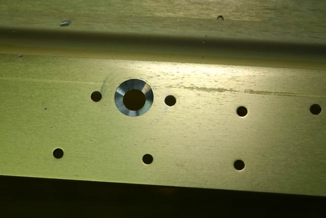
First, you clamp a piece of aluminum angle under a set of platenut holes. Then drill through the center hole with a #30 bit, being very careful to keep this hole centered concentrically with the larger screw hole. Then, match drill the two rivet holes with a #40 bit. The result is this:
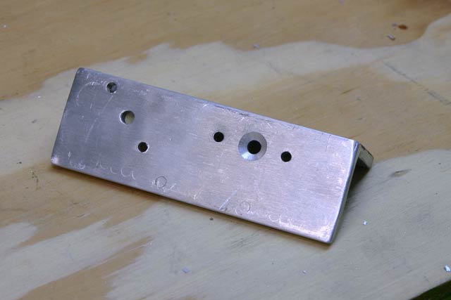
Since some of the holes are parallel to the spar and some others are at 45 degrees, I drilled both patterns in one piece of angle (some other holes are at “-45” degrees, so I used a separate piece of angle for those). — Oh, and don’t pay attention to the countersinking on the middle hole on the right. This happens as you start countersinking and the spar hole gets enlarged.

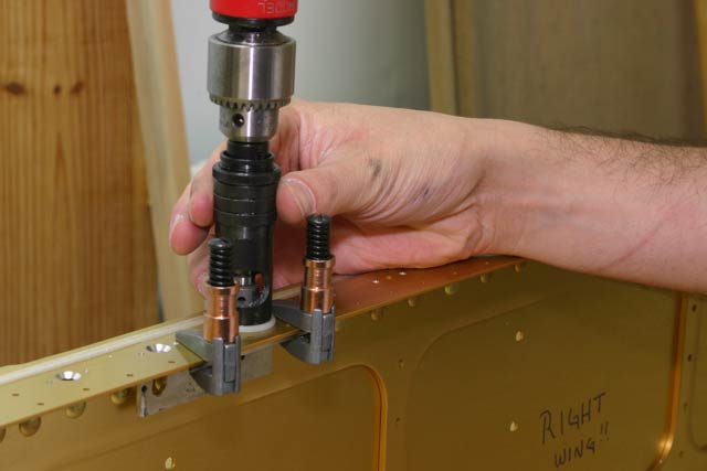
Then I used cleco clamps to hold the angle in place, and removed the clecoes (because the countersink cage won’t fit with the clecoes in place)

Finally just place the countersink pilot through the pilot #30 hole and countersink away! No wobbling, no chattering, etc.
I then used a piece of aluminum dimpled for a #8 screw to make sure it would sit flush against the spar flange.

Of course, I then tested with an actual screw, and didn’t like what I saw at all 🙁

Even if the dimpled piece doesn’t sit exactly flush now, it will be flush once the screw is holding it down.

Oh yeah, did I mention how many freaking holes there are in this thing??