Starting on the Center Section July 1st, 2010
The center section is the main bulkhead in the fuselage. The wing main spars attach to to the fuselage here, as well as the seats, control columns, etc.

There are a bunch of little brackets, angles, etc, that need to be drilled and riveted to this bulkhead.
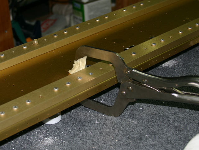
Then there are the two doubler bars for some of the wing spar screws. These have two rivets that just keep them in place. There are no holes for the rivets in the bars, so you have to use the pre-punched holes in the center section as guides. To drill the holes, I put two bolts through the bolt holes, and then clamped the bars to the center section. I then started the hole with a hand-held drill — just enough to know where the hole center should be.
I then took the spacer bar to the drill press to finish drilling the hole. This guarantees the hole will be straight.

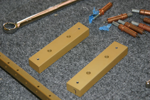
And here are the two bars with the rivet holes
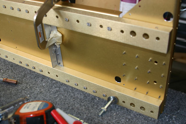
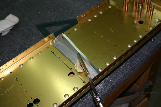
Finally, there are two reinforcement angles that need to be drilled to the center section. To drill these, I just drew a line down the centerline of the angle, and lined up the markings with the pre-punched holes on the center section. Note the bolt on the lower right — there is one on each end to hold the bulkhead upright on the table. This will of course come out when I’m done riveting all the ‘accessories’ to it.
Center Section – Control Column Mounts July 1st, 2010
The control column mounts is the pivot point for the control stick, and where the entire control system for the ailerons and elevators comes together. They come with a bearing pre-installed, so all there is to do is drill holes for the bolts that will fasten them to the center section.
I drilled the first hole on a drill press to the dimensions given on the drawings. For the second hole, I positioned the piece on the center section and made sure the mount was at 90 degrees to the flange of the center section.

I used a vise-clamp to hold it in place, and then turned the bulkhead over.
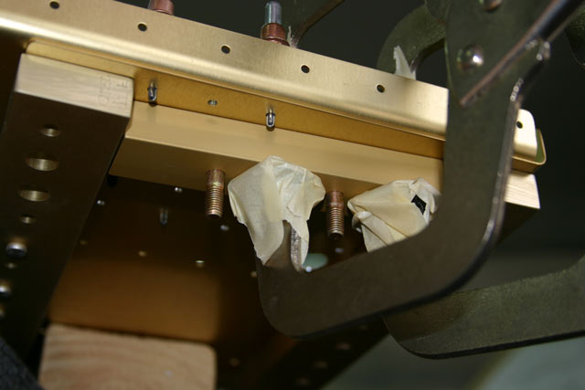
Before placing the mount on the center section, I drew a centerline as well as a line showing the minimum edge distance.

I then started the hole with a hand-held drill as shown below. The aluminum angle is very thick, and I did not think I could drill a straight hole by hand. I took the mount off the center section and finished drilling the hole in the drill press.

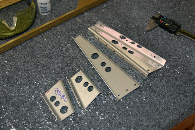
Here is the part after drilling both holes and marking the material to be removed for weight savings.

I then used a bandsaw to cut away most of the material. Here is the obligatory picture of me actually doing the work.

And this is the rough-cut part:

Finally, much nicer looking after polishing in the Scotch-Brite wheel.

Assembling the Firewall Angles June 29th, 2010
Here is the firewall with all of its angles, bits and pieces clecoed together. Note that I also have the thick angle brackets clamped in place, as I was about to match-drill them to the firewall along with the rest of the angles.

Once I had everything clecoed together, I noticed the two angles that have a pre-formed bend (F-601-N) did not fit very good. Apparently this is a common issue with these parts — the type of bend applied doesn’t really go with the shape of the angle…


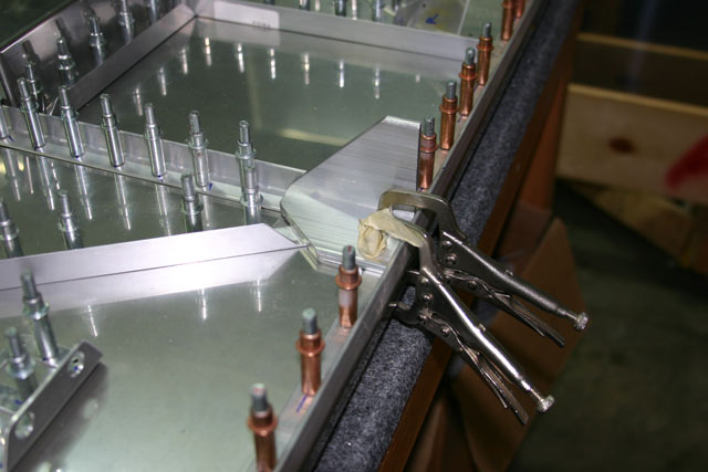
The two recommended solutions are to either add shims, or try to ‘fix’ the bend. I didn’t really like the shim approach, since is would require more of a wedge-shaped shim. So, I decided to try to fix the bend. I used my 2X rivet gun with a mushroom set with the angle clamped as shown below. When I was done, the gap was practially gone. The angle looked a bit scuffed, but I went over it a few times with a maroon scotch-brite pad, and it looked like new.

Starting on the Firewall: Building Brackets April 20th, 2010
This is the very first part of the fuselage construction!
The first task is to make two brackets out of angle aluminum. These get riveted to the firewall near the bottom center, and will tie in to rest of the fuselage. This is thick 3/16″ stuff, but I put it through my little bandsaw with some cutting oil, and it went through it like butter.

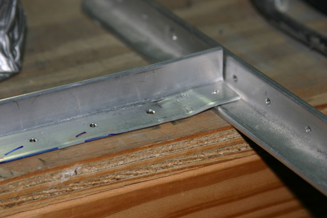
Here are the two finished brackets – nice and shiny.

One quick note here — when these brackets are lined up and drilled to the firewall, the bottom rivet holes will be very close to the edge. In my case, they were about 0.014″ closer to the edge than the minimum edge distance of 2x the hole diameter from the hole center. I called Van’s Aircraft about this, and they said this was OK.