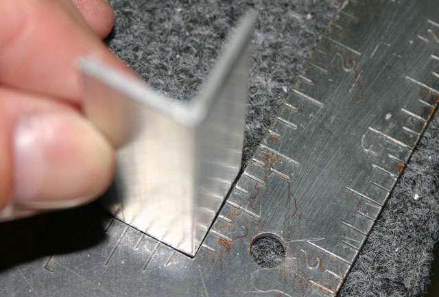
Bending the F-729C Angle September 19th, 2010
This little angle serves as support in the F-706 bulkhead assembly. The drawings show how it has to be bent to 88.5 degrees (rather than 90 degrees). So, how do you bend this thing by 1.5 degrees? Well, I just clamped it to my vise and cranked a little at a time until it was about right!

I checked it against a square and measured the distance between the angle and the edge of the square. I was looking for 19.5 mils, if you’re curious 🙂
Drilling the F-705 Canopy Angles August 30th, 2010
These two brackets start out as 3/16″ aluminum angle. Once they are cut the right length, they are match drilled to the top of the F-705 bulkhead.
After screwing one of these up, here is the correct procedure to match drill these angles.
- Clamp the angle to the F-705F channel as shown below, but only drill the holes on the forward side of F-705F! (i.e., the holes facing up on the picture below)

- Now insert the F-705D side channel and the F-705E doubler between the F-705F channel and the F-705G angle. Cleco and clamp everything in place, and match drill the holes on the top side of the F-705F channel (the holes on the right face of the channel in the picture below)

The result is a bunch of nice holes. If you forget to insert the side channel/doubler, you end up with misaligned holes on the top face of the angle (on the right if you look at the picture below). At the same time, it is very cumbersome to try to align the top channel, side channel, doubler and angle all at once with no holes on the angle.

Finally, once all the holes are match drilled, you can cleco the angle and draw where the oval slot should be. I started the slot by drilling two holes, and then used a dremel tool to give it the final shape.
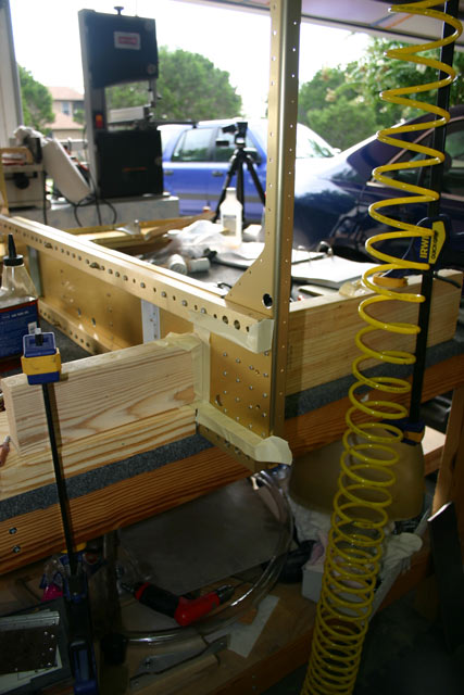
Seat Back Adjustment Brackets on F-705 August 29th, 2010
The seat backs have a clever two-position adjustment mechanism. The top of the F-705 bulkhead has two slots. A tab that holds the seat back can be adjusted to one of the two positions depending on how much you want to lean back.

The first part of making this part of the bulkhead was to put a very slight bend on the two F-705K aluminum strips that act as guides. This was a good excuse to buy a little bending brake from Harbor freight. It is as simple as it gets, so I figured this one thing from Harbor Freight would be OK :-).

I clamped the F-705K aluminum strip in place, and started cranking on the brake. Just a little at a time to get the right bend angle.
Here is a closeup of the F-705K after the bend was complete.

The next step was to take the F-705L shim and match drill it to the top of the bulkhead.

Then came the tricky part. The F-705J angle has to be drilled to the side of the bulkhead, but has to sit 1/8″ from the top surface (refer to the drawing at the top of the post). I used some 1/8″ angle as shown below just to the set the right distance. After the F-705J was drilled and clecoed in place, I simply pulled out the 1/8″ angle.
Finally, here are two shots of the entire assembly clecloed together.

Rudder Pedal Cable Guide August 8th, 2010
After taking the tailcone apart prior to priming, I decided it was a good time to dimple the hole used to hold the rudder cable guide.

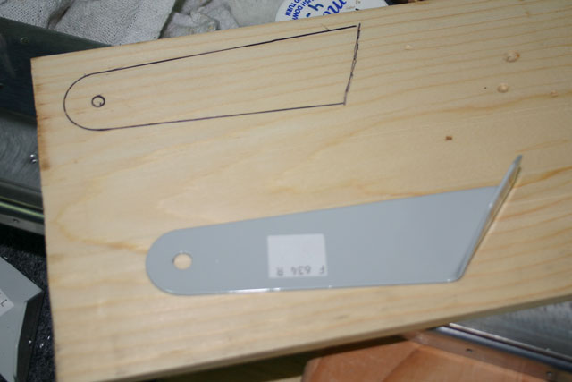
Drilling F-634 Seat Belt Brackets July 27th, 2010
The seat belt anchors do not have pre-punched holes, so they have to be lined up with the holes in the F-705 bulkhead. Each anchor is made up of two F-634 brackets. To attach the anchors, I first drilled a hole in the left brackets as shown in the plans. I then made a spacer out of wood in the shape of the bracket to position the right brackets.
With one side bolted to the bulkhead, and the spacer in place, I put a bolt through the opening where the seat belt would normally attach to keep the two brackets aligned.

I used clamped the right bracket to the F-705 bar with a block of wood to give it some support, turned the whole thing over, and match-drilled the hole.

Then I simply repeated the process for the four anchors, and put all the little brackets away for a while!

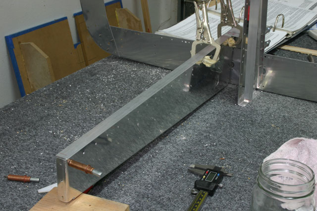
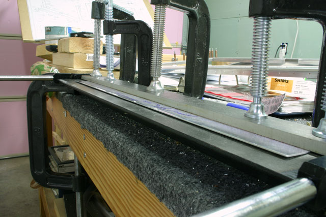
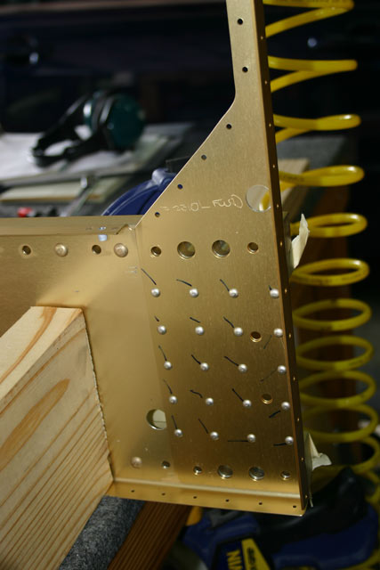
Trimming F-705C Rear Spar Fork July 25th, 2010
The two F-705C form a ‘fork’ that the rear spar bolts into. The inboard end of the F-705C gets trimmed to save some weight. I drew out the patter to trim out, making sure there were at least 0.25″ from the center of the hole to the edge.
I used the bandsaw to remove most of the material, and then used a hand file to round out the end. Unfortunately, I can’t find any pictures of the finished part!!
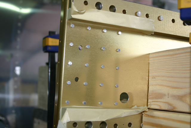
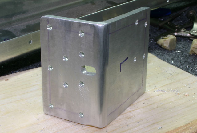
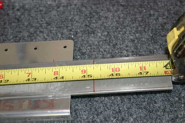
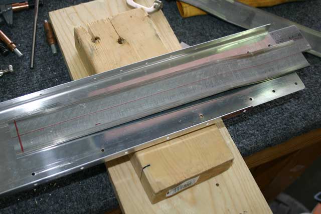
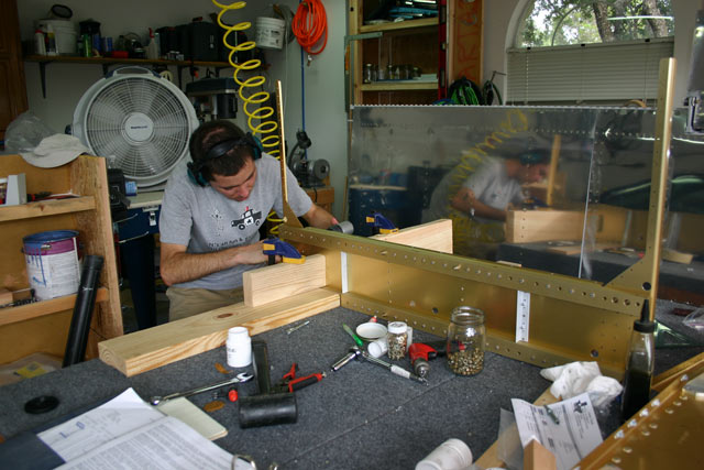
Fabricating F-705B Doubler July 24th, 2010
This doubler bar is where the wing rear spar is bolted to the fuselage, as well as the seat belt anchors. The picture below shows how a single bolt through this bar attaches the wing rear spar to the fuselage. The distance from the bolt to the edges is critical. The drawings call for the bar to be 45-3/32″ long.

I started out by measuring 45-8/32″ to get 5/32″ of ‘headroom’ before cutting.
This is my el-cheapo abrasive cutter — makes these kinds of cuts very easy.

After the bar was cut to the right length, I used the drill press and the lower piece of the bulkhead to drill all of the holes.

Here is the F-605C, which goes on top of the F-705B bar. This one is a little long as well, so it had to be cut down to length.
Finally, here are all of the bottom F-705 pieces , including the little spacer bar.

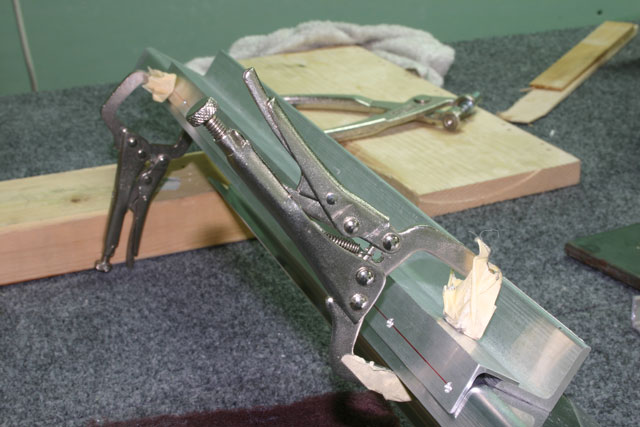
F-705 Real Bulkhead Spacer July 14th, 2010
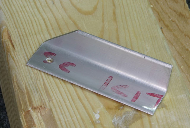
This little bar goes between the ‘fork’ that accepts each wing’s rear spar. We start out with a piece of aluminum bar, and cut out two pieces:
![]()
I am still surprised how well my Sears bandsaw cuts through aluminum. I just use a little cutting oil and it goes through like butter (well, not quite, but still very effortlessly).
![]()
One of the corners needs to be filed about 1/32″, so I just clamped in a vice and filed a little at a time until it matched the dimensions on the drawings.
![]()
Here is the end result. Nice and shiny…
![]()
Center Section – Control Sticks July 8th, 2010
The control stick assemblies mount on the center section, and tie the stick to the elevators and ailerons. The first step is to trim the little brass tubes to size. These go inside the main stick assembly, and get a bolt through them. The brass tube stays in place, and the stick assembly moves around it.

This arrangement is very similar to the aileron bellcranks, so I used the same technique — drill a hole the size of the tube on a piece of wood, then notch out some of the wood to make sure I could get the tube out. Then insert the tube in the hole, clamp the hole thing to the drill press, and ream the inside of the tube to 3/16″

Next, I installed all the hardware on the control column mounts, and reamed out the holes to 3/16″. These holes are already drilled to size, but the powdercoating makes them slightly undersized.

This shows the hardware required for the rod that connects the two sticks together. Looks like I need another washer on the right of the bearing.
This is the entire assembly. The bottom of the sticks will connect to the aileron control rods, and the center fork will connect to the elevator control rod.

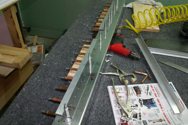
Riveting Center Section July 3rd, 2010
The center section has a bunch of ‘accessories’ — nutplates, angles to hold the floor planers, and the channels that will eventually rivet to the side skins.
Most of these rivets cannot be squeezed, so I had to figure out a way to hold the center section halves in place while using the rivet gun. Simple enough — I used some 2×6 and 2×4 pieces I had laying around. I just put some tape on the ends to protect the work, and notched out a small area to clear the bit rivets set at the factory.
The side channels include holes for the bolts that hold the wings to the fuselage. These are close tolerance bolts, so it is very important that they absolutely lined up. To make sure everything was perfectly aligned, I first inserted four of the bolts through the hole (not all the way, as you can see — just enough to line up the holes), and then used a cleco in every hole. After all the clecos were in place, I removed the bolts and started riveting.

Another picture of me doing actual work…
After riveting the wing skins, it’s so nice to have full access to both sides of the rivets!
Notice the tape along the bottom of the center section to protect it from the rivet gun.
Finally, more pretty rivets.