Finishing the Rudder, Part 2 September 16th, 2006
Ok, it’s all done!
Have I mentioned that bending the leading edge was a beatch? I got my brother to help we eventually got it. The center section looks less-than-perfect, but definitely not too bad.
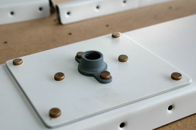
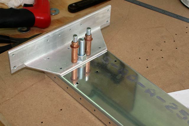
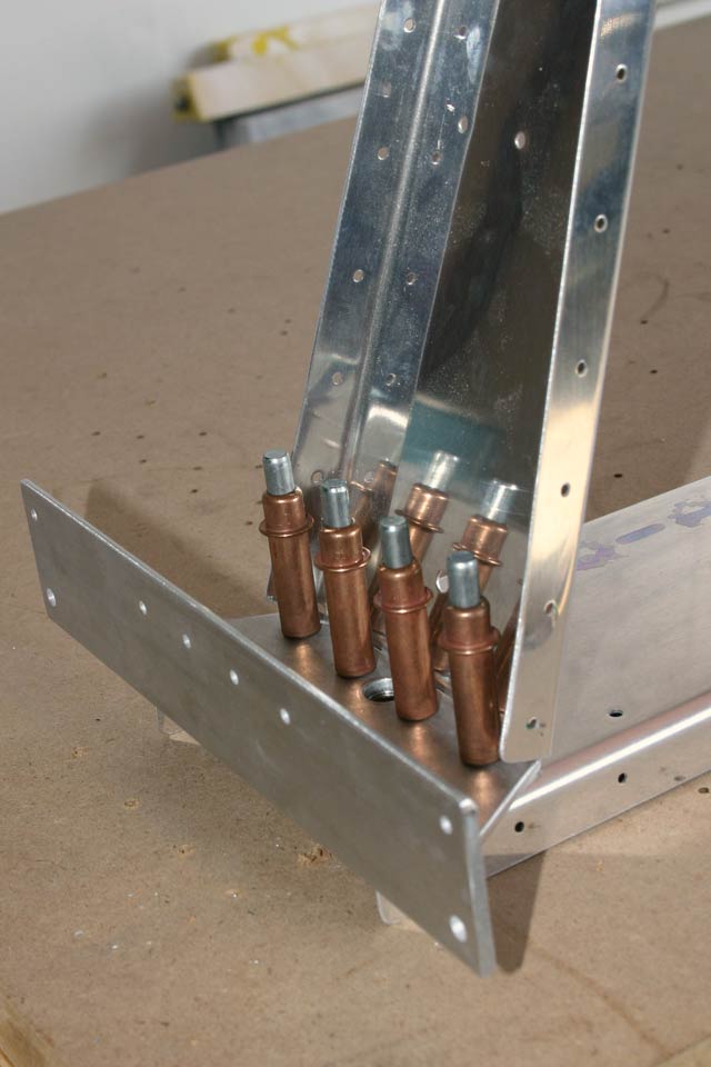
Screwing the Rod-End bearings into the platenuts requires a special tool. Since the platenuts are squished for extra retention, you can’t just use your fingers for these things.
First I built a tool from PVC, to keep from damaging the rod-end bearings:

This tool worked for about 50% of the way in. At this point, it started slipping, so I had to build something else. This time I used a cutting disk on a dremel tool to cut two slots on a 14mm hex socket. After polishing it, it worked great for screwing the rod-end bearings the rest of the way as called out in the plans:

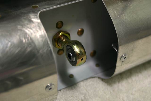
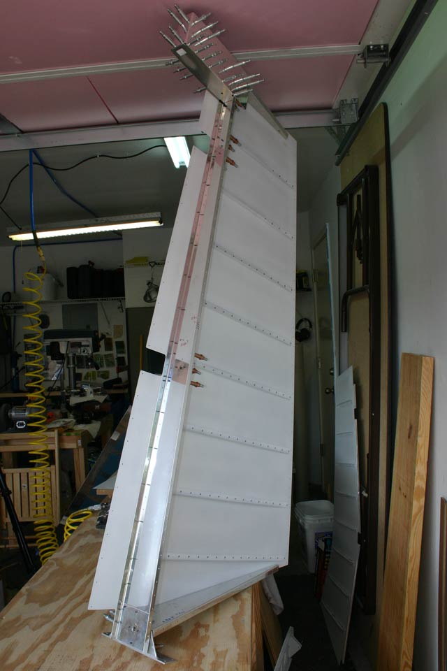
After these were in, it was time to test fit the rudder to the vertical stabilizer!
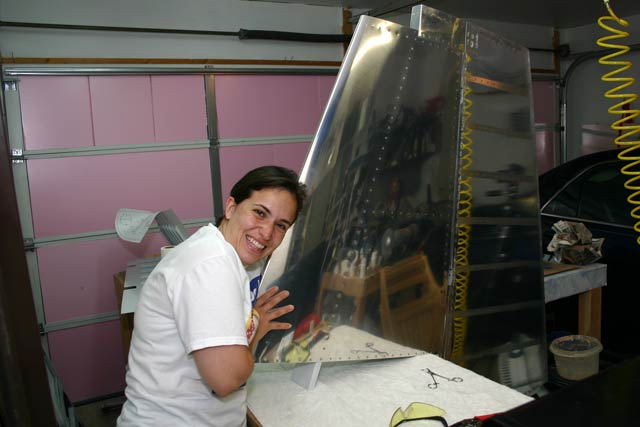
Fabiola says this thing is starting to look like an airplane!

Finishing the Rudder, Part 1 September 11th, 2006


Gluing the Rudder Trailing Edge August 20th, 2006
It’s been in the 100’s here for the last few days here, so I haven’t been too inclined to go into the garage and work on the plane.
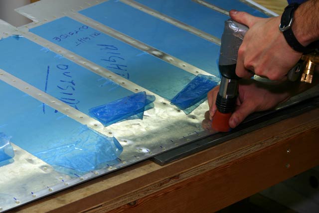
I finally got around to gluing the trailing edge of the rudder. I bought the fuel tank sealant that comes in a tube dispenser. I quickly realized this was a mistake. I probably used 5% of the material in the tube, and the rest went to waste. If was to do this again, I’d want to buy the 1 ounce bottle instead.
Anyway, the stuff is gooey and nasty. The only way to to this is with a helper and lot of disposable gloves. I got my brother to help, and it wasn’t too bad. He applied the sealant to the wedge, and I smeared it more or less uniformly over the wedge. When we had one side covered in sealant, I turned it over and held it up with one hand while he applied the sealant to the ‘other side’. I used my free hand to smear it.
We then slid the wedge into the rudder and started putting a cleco in every hole.
To keep the clecos and the aluminum angle from sticking to the rudder, I used petroleum jelly (i.e., vaseline) on the surface on the angle, and on the clecos.
Here’s the rudder all clecoed and waiting to cure. There is about half an inch between the topmost hole and the tip of the rudder, so I used a clamp to make sure the skin stuck to the wedge.

Riveting Right Elevator Stiffeners August 1st, 2006
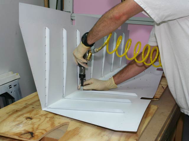
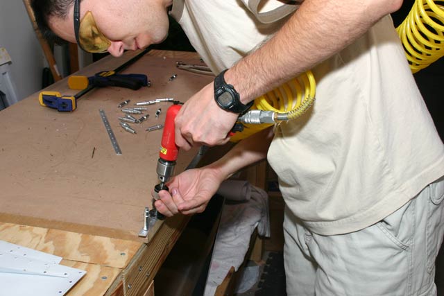
I started to rivet the right elevator stiffeners while I wait for the chip chaser for the rudder. The only thing to note there is that the last rivets closer to the trailing edge are a major pain to set. You basically have to hold the skin open at near 90 degrees while riveting. I was wearing latex gloves mainly to keep sweat/grease/etc away from the nice white primer. As you can see in the picture below, I was holding the gun in such a way that my knuckles rested on the open skin, to prevent the gun from rubbing against it. This worked out pretty good as there were absolutely no marks on the skin when I finished. The knuckle on my middle finger, however, didn’t fare as well. The vibration against first against the skin, and then against the stiffener, basically rubbed the skin off it 🙁 . While this technique definitely works, I would use my thick rawhide gloves instead of latex gloves next time around.
Also, notice how the skin gets badly distorted as I’m riveting in the picture below. I didn’t really notice this until I saw the picture.
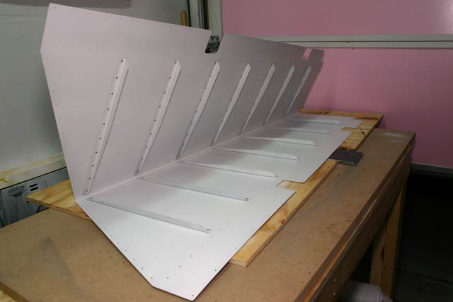
As you can see in the next picture, the skin turned out just fine. I think I’ll do the stiffeners for the left elevator next.
More Rudder Work July 29th, 2006
Here are the two skins riveted to the frame. The four rivets on each side that hold the rudder horn brace are kind of hard to set. The plans call out optional pop rivets. However, these require a larger hole. I went ahead and drilled to #30, but had some aluminum chips get between the sheets. I tried using a thin screwdriver, but I really need a chip-chaser. I decided to order one, so I’ll just wait for it and work on the elevator a bit. Also, the horn brace is held to the rib and to the horn with LP4-3 and LP4-4 rivets. I didn’t have enough of these, so I ordered them from Aircraft Spruce at the same time as the chip chaser. Nobody else seems to call these rivets LP4-3, etc. However, Aircraft Spruce carries them as BSPS-43 and BSPS-44, or so they say at http://www.vansairforce.com . We’ll find out!

If I were to do this again, I would probably drill the horn brace holes to #30 before putting everything together, so each hole can be cleaned properly.
Once I get these rivets I will have a few more rivets to set and then I’ll be ready to do the trailing edge.
Assembling the Rudder skeleton July 27th, 2006
I was able to reach just about every rivet with the squeezer, with the exception of the two outer rivets on the lower rib (see the picture on the bottom).

Countersinking Trailing Edge July 18th, 2006
The trailing edge is an aluminum wedge that holds the two skins together. This part is countersunk on both sides.
Match Drilling Rudder July 10th, 2006
I had all the required pieces to put everything together and match drill all of the holes. Here is a picture of the assembled rudder

Next I’ll have to take everything apart, deburr, dimple, and countersink the trailing edge wedge.
Assembling the Rudder July 5th, 2006

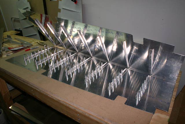
Drilling elevator stiffeners June 28th, 2006
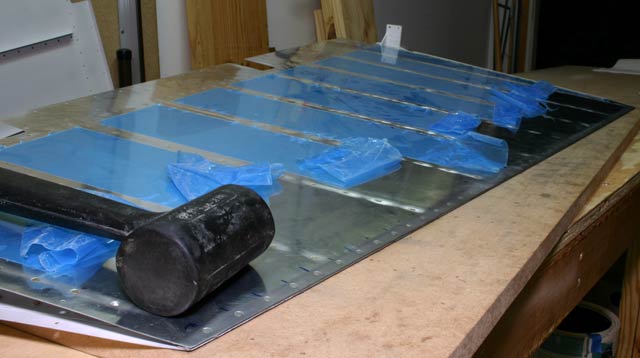
All the stiffeners for the right elevator are done. The elevator skin has also been deburred. The next step is to match drill the stiffeners to the skin. Since the skin is pre-bent, drilling the last few holes closest to the trailing edge is very difficult. I found it much easier to bend the skin back if the stiffeners are clecoed on. So, I clecoed the stiffeners on one side of the skin, and match drilled the ones on the other side. I then switched sides.
The only other things to note is that the last hole on three of the stiffeners on each side are drilled in assembly with the skin. No big deal, just have to be drilled from the outside.