Preparing the Ribs March 2nd, 2006
Two of the ribs need to have their flanges cut up so they fit in the spars. I used the sheet metal shears to remove most of the material, followed by the scotch-brite wheel and emery cloth to smooth out the edges.


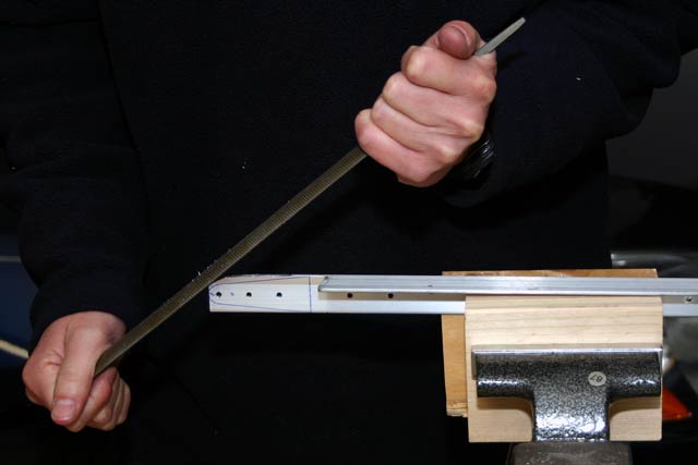
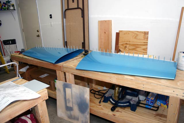
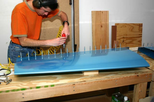
Because of the manufacturing process, the ribs end up with a bit of a warp on them. They need to be straightened out before installing them. To do this, I used fluting pliers to make small flutes (d’uh) on a couple of places. This makes the ribs nice and straight. In the two pictures below, you can see how the rib warps upwards, and how the hand-seamer is used to straighten it up. You can see a finished rib on the background, sitting flat against the table.


Finally, after the ribs are fluted, deburred, etc., the skeleton for the Horizontal Stabilizer comes together!!

Bending and Drilling the Front Spar March 2nd, 2006


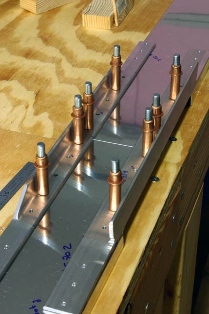
After bending the spar, I assembled it with the two reinforcement angles, and drilled all the rest of the holes. The final result is shown below.


More Front Spar Work February 26th, 2006
After preparing the reinforcement angles, the spar channel itself has to be bent as well. The spar is also used in the RV8, so it needs to be trimmed for the RV7. The trimming consists of removing a small amount of flange on each side of the channel.
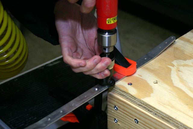
To avoid creating stress points, I first drilled a #30 hole where the flange would be removed. I then enlarged the hole with a unibit so that the edge of the hole coincides with the location where the flange is to be cut off.
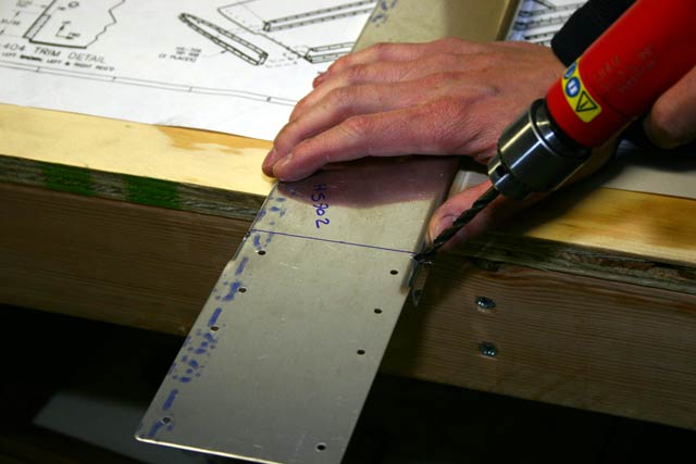
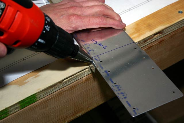
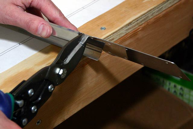
I then used sheet metal shears to cut off the flange. Rather than remove all the material in one cut, I removed a little at a time. This is a trick I learned when I first met with my EAA tech advisor. Instead of having the flange deform as I cut it, the small piece deforms, and the ‘good’ side of the material remains nice and straight.
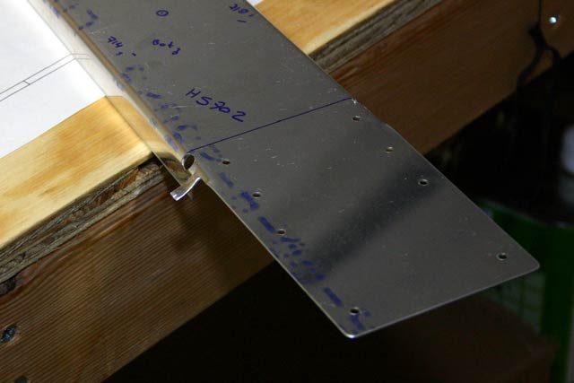
Finally, I used this little tip (see below) on the dremel tool to smooth out the edge a bit. I’ve found this tip very useful for quickly removing small amounts of material.

Finally, I used a Scotch-Brite wheel to polish the edges so no sharp points remain.
Now for the Front Spar.. February 25th, 2006
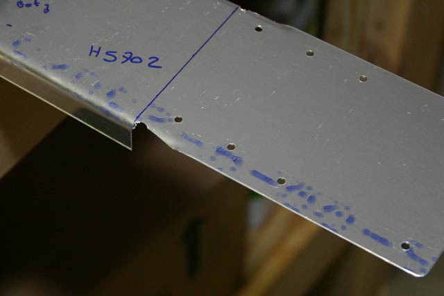
The aluminum angles came from the factory as shown on the first picture below; they were pre-cut and pre-drilled. So, I just clecoed them to the spar and match drilled all of the holes in the center section, except for the four called out in the plans. I marked these with ‘NO’ just so I wouldn’t drill them out by accident.


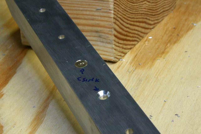
After the angles have been bent, we just need to countersink the center two holes, since these two will have flush-head rivets.
Match Drilling the Rear Spar February 24th, 2006
Now that the spar is nice and smooth, it’s time to match-drill it to the skins. This is pretty simple. Make sure the holes in the skin and the spar match up, and cleco everything together. Next, drill the holes to size #40. The holes are already drilled, just not to the right size. Once every other hole is final-drilled, move the clecos to those holes, and drill out the rest.


Deburr Deburr Deburr… February 23rd, 2006
Deburring basically means polishing the aluminum surfaces to the point where there aren’t any sharp corners, scratches, etc. This reduces the probability of having the piece crack under stress. At this point I’m starting to understand that deburring is going to take a large chunk of the total building time.
Here’s a picture of my favorite way of deburring. I found the mini-die grinder at Lowe’s, and put in the small Scotch-Brite wheel. It does a perfect job every time! A lot smoother than using Emery Cloth. I will probably still use Emery Cloth on the skins and other thin material, though.

Drilling the Rear Spar February 20th, 2006
Once the reinforcement bars have been rounded off and are nice and shiny, it’s time to match-drill them to the rear spar.
I laid the pieces on the table and drilled the outer two holes through the pieces and into the table. This allowed me to cleco everything down before drilling all the other holes. I also put in the brackets that go in the spar, so everything is match drilled in place.

This picture shows how I keep track of what part goes where after I take things apart for cleaning or deburring. I just draw lines at different angles through the different parts. When the parts are put back together correctly, the lines match. Now I gotta figure out how I’m going to keep those lines when I clean things up for priming!
 It may be worth mentioning that when I first placed the reinforcement bars inside the rear spar, it was hard to get the holes to match without having a small gap between the bar and the spar. I went back to the grinder and radiused the bottom edge of the bar just a little bit more, and everything fit perfectly.
Since I had the hinge bracket in place, I match-drilled it as well.

Getting Started on the Horizontal Stabilizer February 20th, 2006
Ok, so I finally started working on the kit!
The first order or business is to polish/deburr the two reinforcement bars for the rear spar. The manual talks about polishing them to the equivalent of #400 grit sandpaper. I wanted to use the Scotch-Brite wheel in my grinder, but wasn’t sure what grit equivalent it is. So, I actually went to the hardware store and got some #400 sandpaper! After trying it out on a scrap piece of aluminum I quickly determined the Scotch-Brite wheel is definitely finer than this.

The idea here is to remove all the grooves, dents, etc., and end up with a nice shiny surface. Here is a shot of the two reinforcement bars after polishing one of them.
